Research Cell
Mechanical and Electronics Related Information and DIY Projects
A4988 is perhaps the most famous stepper motor driver which is usually sold as a complete breakout board. It is small, very cheap, and easily available even in remote electronics markets. It can drive almost any bipolar stepper motor and can deliver up to 2 Amperes of current per coil. However, the operating voltage needs to stay between 8V to 35V max and you will also need to add a heatsink plate if your stepper motor is pulling more than 1A current.
A4988 also offers some extra features such as coil current limitation, and over-current protection, and on top of that it also offers micro stepping just like many expensive stepper drivers. This makes it ideal to use inside small-scale CNC or robotic projects due to which it is very famous among engineering students.
I have received many requests to post a complete guide on the use of A4988 so here it is.
To drive a stepper motor using A4988, you will need two types of power supplies
As for 5V input, you can use any general purpose 5V 1A power supply but for the 8V to 35V power input, you must find a unit that can deliver a minimum 4 Ampere current, ideally, you should have a 5A or higher rated power supply for this purpose.
Regarding the voltage selection, I would recommend you to find out the maximum voltage rating of your stepper motor and choose a power supply voltage as close to that as possible. Stepper motors tend to skip steps if driven at a lower voltage. The maximum stable speed of your stepper motor is directly proportional to your power supply voltage.
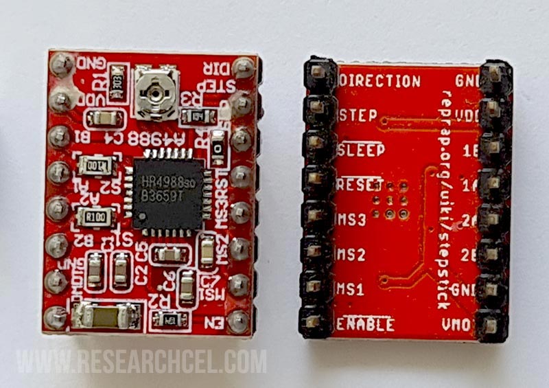
I have added an image within this section that shows the connection details for every pin on the A4988 breakout board. Please take a good look at the image and then read further from this point. You can click on the image to enlarge it.
First, connect the “Sleep” pin to the “Reset” pin using either a wire or you can simply overflow the soldering wire within these two pins as they are placed right next to each other. Now, it is time to connect your stepper motor wires with your A4988 board. Normally, you can find the stepper motor wiring color codes on the body of the stepper motor however if you are unable to find them then you can use a multimeter to find the correct wires using the following method.
There are several types of stepper motors available but I am going to address the two most common types of stepper motors.
This method will work on all 4 wire stepper motors. Set your multimeter to the resistor testing mode and then attach one probe of your multimeter to any of the 4 wires. Now touch the second probe to the remaining wires one by one, one of those 3 wires will show an almost short circuit with the first wire. Mark these two wires as coil 1 and the remaining two wires as Coil 2.
If you have a 6 wires stepper motor then set your multimeter to the resistor testing mode and connect the first probe to any wire. Then touch the second probe to the remaining wires, and you will find that two of those wires will show connectivity with your first wire, note down the resistance value between your first wire and each of those two wires. You need to pick the wire with the greater resistance and mark it along with the first wire as coil 1 and mark the wire that shows less resistance as unused. However, If you find that the first wire shows the same resistance as two other wires simply pick those two wires as coil 1 and mark your first wire as unused.
Now you are left with 3 remaining wires, again do the above procedure with these wires; find two wires from those 3 that have the highest resistance between them and mark those two wires as coil 2 and again mark the third wire is unused. It is a good idea to cover the ends of the two unused wires with duct tape separately so that they cannot touch and create a short circuit with anything.
Find the 1A, 1B, 2A, and 2B pins on your A4988 breakout board and connect the Coil 1 wires with 1A and 1B in any order and similarly connect the Coil 2 wires with 2A and 2B pins. Now it is time to connect the power supply wires but make sure to turn off both power supplies before you start the connections.
First, connect the 5V power supply +V wire with the VDD pin and the -V wire with the GND Pin.
Now connect the +V side of your stepper motor main supply (8V to 35V) to the VMO pin and the -V to the GND pin. (Note: It is better to connect it with the GND pin right next to the VMO instead of the opposite side GND pin).
It is now time to test your A4988 board setup. (Temporarily) Connect the “Dir” pin and the “Step” pin with the “GND” pin (close to 5V) to avoid random jerky movement of the stepper motor. (Dir and Step pins are not pulled down by default so leaving them floating will result in unpredictable jerky stepper movements).
Now power up both of your power supplies and try to rotate the stepper motor rotor with your fingers, if it is locked in its current position then all your connections are good.
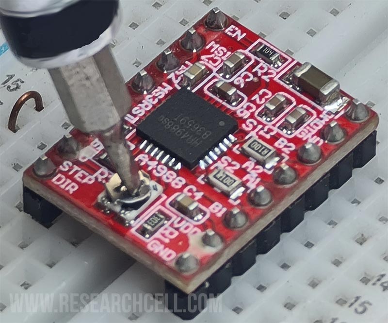
Now it is time to adjust the maximum amperes for your stepper motor using the onboard variable. Turn it all the way to the left (counter-clockwise), now try to turn your stepper motor again, you will note that although it is still locked you can easily move it with a little force, now rotate the variable slowly to the right (clockwise) while still trying to rotate the motor rotor with your fingers until you are almost unable to easily rotate it.
Now leave the variable resistor in this position and wait for 5 minutes and see how hot the motor gets, if it is too hot then lower the current a bit by rotating the variable to the left.
If you feel it is still very cold then you should rotate the variable resistor a bit more to the clockwise direction and then wait for 5 minutes and check the motor again. The idea is to get the maximum torque without burning the motor.
By the way, some people also refer to this current adjustment as voltage adjustment which is wrong, this variable only changes the current which in turn changes the voltage on the stepper motor coils. The volts will keep changing during the micro-stepping cycles while the current will stay constant.
It is better to connect an ampere meter in the series of one coil while doing the above procedure and also make sure that A4988 is in full step mode (MS1, MS2, and MS3 disconnected). The current drawn should be lower than the maximum allowed limit of your stepper motor. Also, the A4988 can handle 2A current at max that too with a heatsink. If your stepper motor tried to pull more than 2A from A4988 then it will start to throttle the current which will result in missing steps. It can even damage the IC in the long run since the continuous overheat situation can alter the internal die of an a4988.
Once the current adjustment is done, remove the “Dir” and “Step” pin connections that you temporarily grounded earlier and connect them with your microcontroller, Arduino, or whatever device you are using to control your stepper motor.
Note: Never remove stepper motor wires while the driver is powered, it will almost certainly damage your A4988. I have burnt mine due to the use of a loose breadboard, the stepper motor wires sparked due to the motor vibration causing permanent damage to my A4988.
A4988 also supports microstep technology. Normally upon receiving a step pulse, A4988 will move your stepper motor one step ahead towards your selected direction but you can also configure it to move half step, quarter step, Eighth of a step, or even sixteenth of a step upon receiving a step pulse. This can be configured using MS1, MS2, and MS3 pins. Here is the configuration chart:
| MS1 Pin | MS2 Pin | MS3 Pin | Step Resolution |
| Low | Low | Low | Full Step (Default) |
| High | Low | Low | Half Step |
| Low | High | Low | Quarter Step |
| High | High | Low | Eighth Step |
| High | High | High | Sixteenth Step |
*”Low” means disconnected while “High” means connected to 5V.
Microstepping technology can be used to reduce stepper motor vibrations and sounds. The higher step resolution you use, the less sound the motor will make and the smoother it will move. But it comes at the cost of lowering the torque so you will need to find a balance between both the torque and the smoothness. Also, make sure that your stepper motor supports microstepping before using it.