Research Cell
Mechanical and Electronics Related Information and DIY Projects
DRV8825 is a very popular stepper motor driver that can easily drive most stepper motors in use today. In this article, I will tell you how to use DRV8825 in your projects and what are the reasons that made it so popular. If you are building a project that requires stepper motors then this article will greatly help you.
If you are using small or medium-sized stepper motors in a project, then DRV8825 is probably the best stepper motor driver for you. It comes already installed on the breakout board that too at a very low price. Despite being cheap, DRV8825 still has almost all the features that are found inside much more expensive stepper motor drivers. In addition to that, it can be easily implemented with Arduino or any other type of microcontroller.
Note: whenever I refer to DRV8825, it actually means DRV8825 with a carrier or breakout board. That is because DRV8825PWPR alone cannot work and it requires some additional components to work which are already attached to it on the breakout board to save our time.
This tutorial will cover everything related to the DRV8825 breakout board and can serve as a datasheet of the DRV8825 breakout board. If for some reason, you need Datasheet for “DRV88225 IC only” then you can get it from the Texas Instruments website.
DRV8825 IC or Module has the following specs:
| Minimum Input Voltage to Operate | 8.2V |
| Maximum Allowed Input Voltage | 45V (40V Recommended) |
| Maximum Current with Heatsink | 2.5A |
| Maximum Current without Heatsink | 1.5A |
| Microstepping Modes | ½, 1/4, 1/8, 1/16, 1/32 |
| Minimum Pulse width duration | 1.9 microseconds |
| Supported Stepper Motors | 4, 6, and 8 wires Bipolar stepper motors |
| Current Limiting | Yes (PWM Based) |
| Thermal Heat Protection | Yes (Current Throttling) |
| Short Circuit Protection | Yes (Shutdown) |
| Under Voltage Protection | Yes (Lockout) |
| PWM Frequency | 30 Khz (Pulse width modulation) |
| Interfacing Voltage | 3.3V, 5V |
| Supported Controllers | Arduino, Microchip PIC, Raspberry Pi, PC Parallel Port |
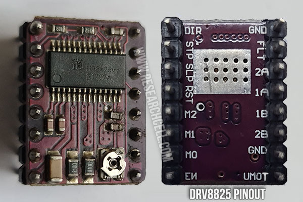
As you can see in the image, the DRV8825 breakout board has 16 pins that are divided into two groups. The 8 pins on one side consist of the stepper motor connections and the power supply connections while the other side pins are the control pins. These pins are usually connected to Arduino or a Microcontroller.
This distribution of DRV8825 pins is very useful as all the high-power wiring is confined to one side which makes the control wires on the other side free from any interference that could be caused by high-power wires. I think the engineer who designed this breakout board definitely deserves a pay raise. 😊
Here is the DRV8825 Pins chart:
| Pin No. | Function | Pin Status |
| Pin 1 | Enable Pin (Setting it high will disable the board) | Inverted |
| Pin 2 | Micro Stepping Bit Pin 1 | Normal |
| Pin 3 | Micro Stepping Bit Pin 2 | Normal |
| Pin 4 | Micro Stepping Bit Pin 3 | Normal |
| Pin 5 | Reset Pin (Can be set high to restart DRV8825) | Inverted |
| Pin 6 | Sleep Pin (Can be set high to put the stepper motor in sleep mode) | Inverted |
| Pin 7 | Step Pin (Setting it to high will rotate stepper motor one step or microstep to the direction set by the direction pin) | Normal |
| Pin 8 | Dir Pin (Setting this Pin to high or low will set the stepper motor direction to clockwise and anti-clockwise) | Normal |
| Pin 9 | Ground Pin (Ground pin of the breakout board) | Normal |
| Pin 10 | Fault (Triggers with thermal or overcurrent-based shutdown events) | Inverted |
| Pin 11 | A2 (second pin for the coil A of the stepper motor) | Normal |
| Pin 12 | A1 (First pin for the coil A of the stepper motor)A1 (First pin for the coil A of the stepper motor) | Normal |
| Pin 13 | B1 (First pin for the Coil B of the stepper motor) | Normal |
| Pin 14 | B2 (Second pin for the Coil B of the stepper motor) | Normal |
| Pin 15 | Ground Pin (-V for the stepper motor power supply) | Normal |
| Pin 16 | VMOT (+V for the Stepper Motor power supply) | Normal |
DRV8825 has a built-in voltage regulator therefore we don’t need a logic power supply for it. The main stepper motor’s power supply will suffice. Connect your stepper motor wires with Pin 11 to pin 14 and then connect Vmot and Ground pins to your stepper motor’s power supply and power it up.
If everything goes as expected, this should immediately lock your stepper motor in its current position. Now you can use the control side pins to control your stepper motor using Arduino or any Microcontroller. You can easily download the library for DRV8825 depending on the Arduino board you are using.
In case you want to write your own code, you just need to control two pins to control the stepper motor. Every time you send a high pulse to the “Step pin”, it will rotate the stepper motor one step (Or Microstep) clockwise or anticlockwise which can be decided by setting “Dir pin” to high or low.
Note: If your power supply is a bit far from the driver then it is highly recommended to add a 1000uf capacitor with the VMot and Ground pins to avoid voltage spikes caused by stepper motor movements. It should be as close to your DRV8825 as possible.
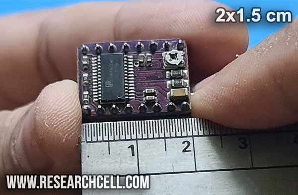
The breakout or expansion board of DRV8825 is 2cm (0.8 inches) long and 1.5cm (0.6 inches) wide. It weighs around 2.15g with connection pins. Without connection pins, the weight is reduced to around 1.6g. There are 16 pins or pin holes on the board in total. These pins are 15mm apart. The color of the control board is purple.
Normally each cycle of a stepper motor consists of 200 steps with each step being 1.8 degrees. However, microstepping makes the further division of each step possible. If we divide every step into two then it will result in (200×2) 400 steps in a full 360-degree rotation of a stepper motor. DRV8825 allows us to divide each step up to 32 times which means we can divide each rotation into 6400 steps. Microstepping makes the stepper movements smoother and more precise which is a necessity in most CNC applications.
Below is a chart that will help you configure the microstepping of the DRV8825.
| M0 | M1 | M2 | Microstepping Mode | MicroSteps per Rotation |
| Low | Low | Low | Full Step | 200 |
| High | Low | Low | Half Step | 400 |
| Low | High | Low | 1/4 Step | 800 |
| High | High | Low | 1/8 Step | 1600 |
| Low | Low | High | 1/16 Step | 3200 |
| High | Low | High | 1/32 Step | 6400 |
| Low | High | High | 1/32 Step | 6400 |
| High | High | High | 1/32 Step | 6400 |
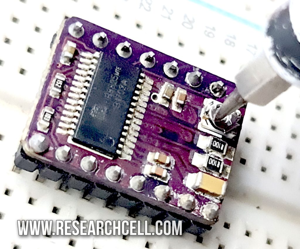
DRV8825 can limit the current supply to the stepper motor coil and you can adjust this limit with the help of an onboard potentiometer. Here are the details of this procedure.
For proper DRV8825 current adjustment, we first need to find out the maximum current rating of your stepper motor. Usually, it is written on the stepper motor itself. Divide this current rating by 2, that is because stepper motors usually have 2 coils. This will give us the maximum current rating of each stepper motor coil.
Now we will power up the DRV8825 and check the reference (Vref) voltage at the center (wiper) of the potentiometer. We can change the Vref voltage by rotating the potentiometer and this will directly affect the holding current limit of DRV8825. Here is the formula to calculate the current limit changes occurring:
Current Limit = Vref x 2
Or Current Limit/2 = Vref
So, if your stepper motor has a maximum rating of 1A per coil then the required Vref voltage will be:
Current Limit/2 = Vref
1/2 = 0.5V
So, you should set the potentiometer to 0.5V which will set the DRV8825 holding current limit to 1A per coil of the stepper motor.
Note: It is better to adjust the current limit at least 10% below the maximum rated current to prolong the stepper motor’s life. Also once you have adjusted the current limit, wait for 5 minutes and then check the temperate of your stepper motor to make sure that it is not overheating. If it is overheating then reduce the current limit appropriately.
Caution: Even during normal operation, DRV8825 gets hot enough to burn the skin. Therefore, do not touch the IC while adjusting the potentiometer.
Following are the main differences between DRV8825 and A4988:
| Function | DRV8825 | A4988 |
| Maximum Current | 2.5A | 2A |
| Microstepping Limit | 1/32 | 1/16 |
| Minimum Step Pulse Width Duration | 1.9 Microseconds | 1 Microseconds |
| Separate Logic supply required | No | Yes |
| Maximum Input Voltage | 45V | 35V |
| Stepper Motor Noise Levels | Less Noise | More Noise |
| Price | Medium | Low |
| Fault Pin | Yes | No |
If you are interested, You can visit A4988 Stepper Motor Driver User Guide to know more about A4988.
DRV8825 is very similar to A4988, it can be seen as a direct replacement for A4988. If you’ve used a 4988 in your project then you can increase its performance by upgrading to DRV8825. This upgrade is easier than you expect. Just remove the A4988 from your circuit and replace it with DRV8825 and you are done.
Note: When installing DRV8825, make sure the pins are in the correct order also the power should be disconnected while doing so otherwise, you will burn your breakout boards.
No, unfortunately you can only drive Bipolar stepper motors with DRV8825.
Input range for DRV8825 is 8.2 to 45 volts. Generally, 12 or 24 volt power supplies are easily available in the market. Although you can run a DRV8825 at 12 volts too but the risk of the stepper motor missing a step at 12V is higher compared to 24V. Therefore in my opinion the DRV8825 should be powered by at least a 24V power supply.
DRV8825 can drive almost any bipolar stepper motor as long as it doesn’t exceed 2.5A and 45V. Here are some of the motors that it drove in our testing are
NEMA 17 (2-Phase, 1.8 Degree)
NEMA 23 (2 Phase, 1.8 Degree)
NEMA 11 (2 Phase, 1.8 Degree)
Yes, we have tested DRV8825 at 1/32 microstepping using Marlin. Our 3d printer was able to make good 3d prints.
Yes, DRV8825 can be directly controlled using ESP32. You can make WiFi or Bluetooth enables CNC projects using this pair.
Not without slight modification. You will need to open the 28byj-48 motor and find a PCB on which the center tap of both motor coils is shorted together. You just need to disconnect the PCB connection in between those wires by scrapping the PCB using a sharp object such as a blade. Once both coils are disconnected from the center, you can drive 28byj-48 with DRV8825. Ignore the center tap wire or better cut it from the PCB and use the 4 remaining wires to connect to your DRV8825.
Note: To be safe, double-check that both coils are not shorted together using a multimeter or you can damage your DRV8825.