Research Cell
Mechanical and Electronics Related Information and DIY Projects
A power inverter is a very useful device that can convert Low voltage from a DC source to high voltage AC. The most common power inverter is a 12V to 240V inverter. Perhaps that is because 12V batteries are common. This type of power inverter usually draws a high current from a DC battery so the battery should be able to supply a high flow of electric current for a long time. Normally lead acid batteries can serve this purpose very well. This current is then converted to a 240V square wave alternative current so that we can power up 220V to 240V electric appliances.
Inverter falls in the category of expensive devices so many people don’t buy it even if they need it. What if I tell you how to build an inverter yourself?
I remember when I build my first inverter, I became so happy that I invited all my friends to see my homemade inverter. I am sure you will feel the same after building it.
Caution: This circuit involves 240V and 500W which can be fatal. You should take all security precautions before building this circuit. Preferably use electricity protective gloves and try not to play with the inverter circuit when it is operational. You must have the necessary knowledge of electronics to build this circuit.
Alright, let us get to work. There are a lot of inverter circuit diagrams available online. Some of them are complex and others are low-performance. I have researched a lot of them but in the end, I had to design my inverter circuit. It is comparable to any professionally made inverter but still is simple enough for you to build.
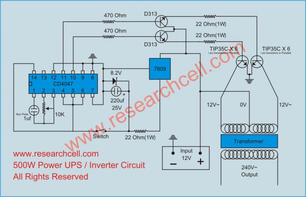
Here is the inverter circuit diagram. It is better to print this entire page and keep it with you while building the inverter.
Expected Cost: It took me less than $100 to complete this circuit.
You will need the following parts.
There is only one variable resistance in this circuit diagram which is used to adjust the frequency of 240V AC output current. You should have a frequency meter to adjust this frequency from 50HZ to 60HZ as per your requirement. Please do not power up any device with your inverter before frequency adjustment. A wrong AC frequency can easily burn your equipment as well as your inverter.
I have used a two-stage regulated power supply to avoid frequency changes with the drop in battery voltage. The first stage is 7809 which is a standalone voltage regulator. It converts 12V DC to 9V DC. Then we used a 22 Ohm resistor and then a Zener diode of 8.2V which forces the current to stay at 8.2V. The 22 Ohm resistor is there just to aid the Zener diode.
The output frequency of this inverter circuit is a square wave which is not ideal to power up inductive loads. If you want to power up any inductive load then use it at your own risk. However, I do power up fans at home using this inverter. The only issue I had with them was a little decrease in the fan speed and the addition of some humming noise.
If you have any questions, please use the comment box bellow.
Thanks for sharing this inverter circuit, can you please tell me which power transistors can I use if TIP35C is not available in my area? Thanks in advance
You can use any NPN transistor here which has power range of minimum 100W and 10A. other examples could be D1047, C2581, 2N3055. however TIP35C is certainly better.
In this circuit which transformer will i use please tell her volts and amp.And Capacitor 220uf and Capacitor1uf volt.thanks
This inverter is automatic or not…please help me to build this inverter…thanks
hello a great thanks…
can this work when the power is off. pls help me…………
how to make the input section a rechargable source that we can power up the equipments even when there is no supply….
great thanksss for the circuit
i want to know the primary, secondary, and the finally stage of your 3kva inverter circuit dragram for learn.i will be greatfull if you can help me
@Farasat Hassnain, you can use a 240v / 12+12 / with a capacity of 40 Amp minimum. Both capacitors should be 25V or above. You can make this inverter automatic using a double relay. I will post an automatic version of this inverter soon.
@Rahul, yes this inverter can work on 12V Battery. You can use any 12V recharge circuit to recharge the battery. Recharge circuits are always separate from inverter part.
@Anthony, In first stage, The CD4047 acts are an accelerator and outputs signal using 470OHM resistors to the D313 transistors, then in second stage these transistors amplify the frequency signal to drive the main transistors and then transfer the signal on the Bases of main transistors using 22OHM 2W resistors and then in the third and last stage, the Main transistors starts to switch as per the given frequency signal . These high current pulses causes the transformer to generate 240V square wave output. I hope that explains every thing, if you have more questions then let me know. 🙂
I want to know that how can we make Transformer 12+12/240 (500W)what is size of its central pole, primary and secondary standard wire guage
Please I need a version that uses 2 relays to make the Inverter automatics, how soon can I have it please.
If use one 40W light and one fan, how long the battery will last?
@Anand, this depends upon which battery you are using. Suppose if you are using a 12V 115AH battery then it will last from 5 to 7 hours depending upon the quality of battery. the calculation is assuming that you are using a 40W tube light and a 120 Watt Ceiling Fan.
Kindly send the circult to email box ,the on your web is legible at all.
Thanks for giving a wonder full information. but i need some more information regarding the transformer as ya have used 12+12/240 transformer. so plz do reply to this.
I am building an electric car. I have a 10 hp 3ph motor. The inverter is out of my price range. What do I need to do to change this diagram to work on my car? Thanks for everyones help.
i think i found this site very intresting, i got what i was looking for though it not exactly what i wanted but this gave me a clue thanks
my inverter is of microtech company.iwrongly connected the wires from inverter to the battery.now it is not working .please tell what should i do & if there any big fault
@Sandeep, It is impossible to say any thing about your inverter unless i see it. You better contact the person from which you purchased it.
@Dave Hotrum, It is not a good idea to use an inverter in such high current applications. You will lose a lot of current during the voltage conversion by the inverter itself. It is impossible to build a 100 percent efficient inverter. almost 25% of the energy will be lost even if you get the most efficient and expensive inverter. I would suggest that you should find 12V or 24V 10HP motor for this purpose. I am sure you will find one if you search for it. I have used one in a machine I made earlier. A 12v or 24v motor will give you more power and running time due the the fact that it will fully utilize the available current directly from the batteries. Let me know if you still have questions. Thank:)
@Ajur, You can use a regular 240 to 12+12 transformer. No need to find a special one. Just keep in your mind the watts you are going to need. For example, if you are building a 500W inverter, you should arrange a transformer capable of dealing with 500W (42A X 12V = 504VA(W)) your transformer should be capable of giving 42A on 12V and 21A on 24V.
hellow!Your inverter diagram is is very easy and efficient.This is a good wook.
I have face some problems during essembling this inverter and need your help.I hope that i will complete my inverter from your gainful opinion.
1.I can’t anderstand the direction of (IC7809) either his collector connect to battry or 22(1w) resistance.
2.If the Transistors TIP35C is not available what is its alternate.
Plaese send me your opinion about above problems as soon as posible.I shall be very thankfull for this.Thankyou
can i use IRf150 in place of Transistors TIP35C.what is your opinion?
please describe your opinion as soon as posible
@Asim. You can use D1047, C2581, 2N3055 or any other NPN transistor with power rating of 10A 100W or above with 45V or above value.
in this 500 watts inverter how much amps in battery please tell me
@muthu. For 500 Watts inverter, it is recommended to use minimum 85 AMP battery. 140AMP or 200AMP will give you more backup time and more balanced power.
CAN I GET VARIABLE RESISTER 10K,CAPACITOR1uf&220uf what is value of volts
pls sir could u make ur circuit more detailed
Hi genious!I have one more problem.
In your inverter diagram there is no led lite to indicate whether the UPS is in working position,chargeing position or trip.
Please give your gainful opinion.
Plaese told from where i give connection to led lights
hellow gnious!
I want to know that either this circuit can charge the battry or not and is this inverter is automatic or not if not plaese post the automatic inverter daigram soon.
I shall be very thankful for this
thanks for sharing your idea..
i am planning to build an inverter using your circuit..
i hope you will guide me building one.
thanks a lot..
hi genius, thank you for circuit. i have few questions:
– could you tell me the direction of the two capacitors? Which side is (+)?
– what is the pin connections of 7809?
– what kind of devices can we run if we use a lower-powered transformer, such as 200 W?
(this is an urgent case. Please help me as soon as possible)
hi genius pls can i no the volt of the capacitor1uf and 220uf
thank for sharing your idea..
iam planning to build an inverter using your circuit,but can i us a IRF150N transistor in place of TIP35C transisor.
please i need answer to this question as soon as posible.
Thanks
6v to 40w inverter circuit
Hi & thanks for sharing your idea with us. I assume that I can use this same plan to build a 3000+ watt inverter but would obviously need to change the values and sizes of the components. Can you please advise me accordingly?
Thank you again for your generosity,
John
hello sir, thanks for sharing your idea on
your inverter very intresting.can i get another circuit that can up to 3kv i will be very happy if i can get it
thanks,
my name is samson jimoh my email is samson_jimoh@yahoo.com
I like ur concept, but i want to know if i can wind the transformer my self and if i can, how
Hi guys, thank you so much for the inverter circuit diagram for 500w. It works so well. Now i have a question, however, because this one produces square wave, can i get one that gives sine wave?. If there is please sent me even via email. Thanks.
Still having a problem understanding the 7809 polarity in this curcuit. I have now placed the 7809 “outside” the curcuit to overcome this problem. The zener clamp shunt the 9V output down to 8.2 volt and supply the CD4047. Is my approch ok doing this? Any ideas?
If i want to use this inverter with acid cell what should be the “VA” of that battery?
@Ratnadeep any thing over 100VA will be good. Please select one Depending upon the your load and the backup time.the more the better.
@Casper, 7809 is actually placed there to decrease the differential load on the 8.2V zener diod. You can even skip the 7809 entirely and can place an extra 22OHM 1 watt resister in place of 7809, the 8.2V zener will automatcially reduce the voltage to 8.2 but it is not recommended though.
@Darlington, i will try my best to post a self tested sine wave circuit as well as soon as possible.
@Tunde, alright i will try to post a tutorial on how to wind a transformer for this inverter circuit as well.
@samson, you can use same circuit for 3KV you only need to rewind the transformer for appropriate voltage. For the power transistors number, just divide your power requirement by 100 and then use that number of TIP35c Transistors on both sides. For example, if your power output is 2000W, just divide it by 100 which is equal to (2000/100) =20 so 20 TIP35C on each side.
i need more circuit diagrams in my mail 4 better construction. i really love the provided circuit diagram.
Hi Genius, thanks for your article. You have helped me nut out how an inverter works. Can you tell me the practical advantages of a sinewave inverter as opposed to a “dirty” modified square wave on?. Will the latter cause over-heating of capacitors in appliances that they are connected to? Will they cause any damage and if they do, in what way?
Thanks a million
Will get back to you after building it
1st ,how can i use FET in place of power transistors?
2nd; how can an inverter work when the battery is diconected after the first suppy.pls help me out.
please i am a student and i ant to construct an inverter in my summer project,i luv your diagram but i am confused on how to connect the TIP transistors can you draw the connections for me through my email; austyn_1@hotail.com i will be pleased.
please how can i wind the transformer to b used and how can the battery be charged .please can you post it to my mail; austyn_1@hotmail.com
please how can i wind the tarnsformer to be used can the battery charged.can you post it my mail
janmuhammad11@live.com thanks
Thanx for the ckt.
Could you tell the polaritys of 2 capacitors?
CD 4047 is not having connected – ve terminal in the ckt.
Could you please clarify.
how do u get make a 24volt inverter from a 12volt..what is really important i should look into
Dear,Si!
I have used power fets 2SK2233 as power transistors. 4 Fets managed to drive the load of 600W. My problem is on how can I change the waves to Sinewve?
Anicet H. Laurent,P.O.Box 5111 Mwanza,Tanzania.
hishakiye@hotmail.com
I have seen what you did,it`s very good,but can you help me with the desing and construction of a unit inverter amplifier in a follow up state.thanks
please,i need all the neccessary information on inverter circult diagram.
hi, i am willing to do ur ckt. but i can not understand that where is the ground portion of ic CD4047. Another problem is that the “0” volt terminal of transformer connected to the positive end of Battery? is it true plz tell me.
Is it possible to find a system where the inverter in retain charges the battery?
plz i need the conection the transistors,and the exertly voltage of the capacitors, can this inverter power a televition and 5x of 100w bulbs?
soon to here from you throug my mail plz.
i want to design a small scale wind power lighting system. Is this circuit is applicable to complete my design. The wind generator connected to 12V battery and than to his circuit. Is it possible?
how to wound transformer for this
the 12v wound first?240v as sec?
I thank for your circuit of inverter so may you send for me circuit diagram of pure sine wave inverter with power of 3000watts or 4000watts.
what are the other components can be used to replace CD4047
i thank you for the inverter circuit,can i use thes inverter to power up to 100W bulbX5 and one television
give the pin details of ic 7809 and how can charging the battery give the circuit.
Hey,
Is there any possiblilty you could tell me what the diffrence is to sine wave and just square wave? also could you send me an automatic version on which i could just plug into say a car socket and run things off?
if you could send it to my email : ironhockey_player@hotmail.com that would be great or just on here as ill check this regulary.
Thanks
@Ray Kompe under my experience, modified sine wave and pure sine wave inverters are almost identical. However modified sine wave inverters cause a little ripple in poorly filtered power supplies, secondly, modified sine wave inverters has less power conversion ratio when compared to pure sine wave. Square wave inverters like this one are thought to be a little harmful for conductive load as well as some digital loads but practically, I think digital powers supplies can easily handle square wave. However conductive load like motors can suffer from low starting surge or heat up under heavy load.
@JanMuhammad, @Johnkennedy, kelvin chibale Inverter is not intended to convert to backup automatically, or to charge battery automatically, you are probably looking for a UPS circuit diagram. I will soon upload one, Please keep visiting.
@Austyno if you hold a TIP35C transistor with its 3 pins upwards and with the front side towards you, the most left side pin is Emitter, the center one is collector and the right one is Base.
@Anicet Laurent @, JASTICE E. NATHANIEL You cannot convert this circuit into sine wave that easily. Right now there are various modified sine wave circuits are available but I am trying to built a simple one. Once done, I will post it here. Please keep visiting.
@Ratnadeep Yes, the center loop or “0” volt terminal of the transformer will be connected to the positive end of the battery.
@Daniel, @Kelvin Okeyson yes this inverter can power up the load depending upon the transformer and the power transistors you use. Please read the article again, you will find the info you want.
@Sara Yes this inverter can server your purpose of 12V to 240V conversion using wind power. And for your second question, CD4047 is a common Integrated Circuit (IC) and can be easily found in almost any electronics market in the world. I am afraid it cannot be replaced with any other IC.
@engel, you can use a standard 12V+12V / 240V transformer if you cannot wind it.
@murugun Please read this article to know about 7809 pins http://www.researchcell.com/general/7809-pin-and-circuit-diagram/
@Shane, I will soon post and article about sine wave, modified sine wave and square wave due to the fact that a lot of people request it. Secondly for you can attach this circuit to your car battery. Just place a high power switch on the 12V positive input. The car automatically charges your battery whenever you start it. However if you don’t often drive then your car battery might get drained due to lack of charging. Try to balance your driving time and your inverter usage. The more you drive, the more battery is charged.
Thanks. Good day, i saw your project kudos to you. Sir, can i use this inverter made to power television, DVD,and radio. Also, how can i continue developing this inverter for sales and even trained people with it.How can i make inverter with 24V input to give 240V output, how can i reduce any noise that might result due to the construction, those components used in your own how will i upgrade their value to suit my construction.
can u forward 2000w inverter circuit to my mail box,use phet
hi, nice to see your work. i want to make an enquiry about the circuit diagram. how can i know the points of connections at any point.i mean how to differenciate between connected points and the unconected points in the circuit diagram:.pls reply me to this email address.call4atta@yahoo.com. thanks
I’m very keen to build this inverter after unsuccessful previous attempts prior to your circuit diagram. I wonder if you can email a clearer circuit diagram. The one you have provided less legible.
Regards
Wenceslas
Aslam-o-alakum
i have used this circuit and found very good result.
but i have a problem in the circuit,that on the inverter the fan speed is not satisfied or the fan speed is low on the inverter.plz sove my two problems about the circuit.
1-if i use the 220nF capacitor then what happen?
2-if i use the irf 150N replacing the npn transistors,so what is new change in the circuit.
@Ahmad Nawaz, my friend, slow fan speeds can be due to two reasons,
1. Inverter Frequency is not 60Hz, you can use the variable to adjust inverter frequency. It is better to get a frequency meter before athttp://www.researchcell.com/wp-admin/edit-comments.php#comments-formtempting this. However you can also put only a fan on your inverter and then adjust the variable till you get the required speed.
2. You can add 10% extra turns on the output side (240V) of your transformer.
I personally think you dont need to attempt the second method, you probably only need to adjust inverter frequency.
Secondly, yes you can use IRF as well but it is a good idea to ground a 10K resister from the bases of IRF150N. However I have tested TIP35C with this circuit not IRFs
Hi genius, i greet you. Just to remind you that you promised to send me your own tested sine wave inverter circuit diagram. Please, post it to this email address together with the automatic relay controlled circuit, darlington_isalano@yahoo.com
Im building a 12-240V, 200w inverter. The problem i face is the current using in 12V side is around 20A. The normal transformer cant wintstand so high current. Could u tell me how ca i build a 200w transformer?
OR
how can i power up to 500w output without using 500W transformer?
THanks…
You are doing a great work at researchcell.com. I have been searching the Net for something like your posting (about inverter) for a long time. I live in an area where power failure is the rule rather than the exception. Tired of gas-consuming and noise-making generators, I made up my mind to find a better means of power generation. I am certain your ‘tutorial’ will help me a lot in realizing my aim. I aim to build the inverter, connect it to a step-up transformer – say 2kv-5kv transformer, using a car-battery as the power source. From the output of the transformer, I want to recharge the battery, using a separate battery-charge. Please, what do you say to this?
i have complete made this circuit with charging battery with battery leval during electict city power off and suported computer supply no brak.
Hi genius,thanks for your commitment in assisting us
with technical information, but i have an issue, your soon is always taking centuries. You promised to upload a UPS schematic diagram and an automatic relay controled inverter, i have been waiting since August 2009 in vain. Is that you dont have them ready? let us know so that we can patiently wait. Thanks.
Hi man thanks for the wonderful knowledge and being generous to every body about power problems.
my comment about this circuit is that (1) it is small and clear am going to try to build it.
my request is please!! degsin for us an auto charger baterry 12v dc which can charge 200Ah baterry thanks.
Hello sir
thank you for sharing such a simple circuit i am going to make this circuit in a day or two & hope that i will get the expected results.
Thank you so much once again, please keep sharing such useful & practical circuits..
Thanks, it is a great project specially for countries of Blackouts and Brownouts. In our country we can have locally build inverters but without power correction factor or overload etc. and they are pure square wave & costly. In my view Modified Sign Wave inverters are better and must cheaper and easier as compared to a pure sign wave. We all will benefit from a Modified sign wave inverter design. If possible please do include overload protection. Thanks again
hELLO!
thanks for your commitment in assisting us
with technical information, but i have an issue, I always taking centuries. You promised to upload a UPS schematic diagram and an automatic relay controled inverter, i have been waiting since June 2009 in vain. Is that you don’t have them ready? let us know so that we can patiently wait. Thanks.
reply to jimohtech@gmail.com
@john, 7809 is a positive voltage regulator. this means that if we give 12V DC or higher (Max 35V DC as per its data sheet) then this IC regulates the output to be exactly 9V. For further detail you may google the data sheet of this IC.
the inverter circuit on this page is deficient. I think we should think of a better way of designing an inverter that can generate a smooth AC signal
Genuis, I marvel at you patience, explaining things that can be found on google without any problems, and answering rudimentory questions.
Can those of you that ask all these questions not interpret a datasheet for a Cd4047? Or a 7809 for that matter, or figure out for yourselves what voltage a cap should have? Give the poor man/lady a break!
And no, you cannot use the cct for a UPS, basta!
More power to you all!
Circuit works great and I managed to substitute some components and increase power to about 700 watts.
waiting for you to upgrade this to Pure Sine Wave output, preferably a circuit that can just piggyback at the output end.
Thanks again. jack Jenson, Malaysia.
This is a very good square wave inverter. I am however waiting for the automatic version with battery charging and automatic switchover to inverter when power goes off. Kindly provide this as promised.
Thanks for you post. Pls can you repost the diagram of the Transistor to make it more clearer.
Hi, I’ve benefited a lot from this site thanks a lot. I have a little problem and I would need your help.
Pleas I’m a student in the university and am about to write my project and my project topic is on “construction of home use inverter.” Pleas if you don’t mind I would like you to send me materials on this.
Sorry for disturbing, I would be very grateful if my request is granted.
Segun
Hello sir/madam
please published 12VDC to 230VAC 1000W(RMS) pure sine wave inverter circuit
Thanks for the circuit…. nice work… your circuit can play between my homemade transformer and 6v battery..
wow the best! i try here in my room working well i used tip31 in 4 pcs and my drive is MPSA42 working very well. thanks for this upload
sir plz make the circuit for outomatic backup.ups back up how i built it< also for pure sine wave plzz sir thanks
Hello Genius,
I plan to build your 500 watt inverter as off-grid application, I will combine with the micro hydro power to charge the battery.
As you mentioned earlier that you would try your best to post a self tested sine wave circuit as well as soon as possible, have you finished with that plan?
BTW, your 500 watt inverter is square wave inverter, what will happen if I load it with tv tube, LCD tv, amplifier, and water pump? please advise me, Many thanks.
Cheers,
Bing
i realy appritiate your intrest to technology and i admire you. I built an inverter of 2000watts and test run it with a 12volt 100amp battery to power five 60watts light bulbs, two phone chargers and step down stereo system and it lasted for only two hours plus. what do i do to generate light with inverter for a longer time?
you have used 4047 in this circuit. Is it a CMOS IC?
I have heard that CMOS ICs are sensitive to physical touch. I we touch this CMOS IC while soldering it, is it possible to affect its performance.
hey very cool project. so just for giggles…if i was off-grid and had need for greater a/c demands a) am i better to have multipul ..say 500w inverters or am i better to build one power house? b) because of the diy prosess i could sevice my own gear and what would be the best parts to have on stock?(burnout fastest)and finally if i build at a nominal power level can i beef up the inverters with simple add-ons or bigger hard ware???? really cool stuff dude
the circuit was very simple and eassy to make with in a day for 230 v at high power(500)w
please shoe me the transformer calculation
I made this inverter and gave to my frinds
Hi; Nice work, can you sent me 1000w 24dc-240ac inverter circuit diagram pls?.
type of capacitor used in circuit electolytic or non if electrolytic then polarity should given…. and which transformer is used 12-0-12 to 240 or 240 to 12-0-12.. i.e. prymery and secondary.. and batterys ah i think it should greater than 115ah..and is compalsury to parallel 6 TIP35C.. why 6.. and can i use normal NPN tran …
hi wizkid.i can’t be thankful enough you for openning our eyes to d world of constant electricity supply through the knowlegde of inveter designe.kindly send to me detailed circuit of a pure sine wave,an automatic 24v-2kw,3kw,5kw, inverter circut iwith indicators and meters.
Warning to all readers – this circuit is completely unregulated, and depending on load, it’s output voltage will vary wildly, possibly damaging anything powered by this device.
I’d recommend a small 240 – 5v transformer, feeding a ~5v signal back to a control circuit.
If the feedback goes over 5v, the duty cycle should be reduced, to keep the voltage close to the required output.
You will also need RC delay circuits, otherwise the control circuit will hunt up and down, trying to maintain the output voltage.
This circuit will work for devices that aren’t too power sensitive, i.e. simple hand tools, but I wouldn’t go plugging my expensive stereo into it…
Nigel.
“nigel.weeks@gmail.com”
Just to agree with Nigel – this circuit is indeed unregulated and of a very basic nature, so I would not advise using it for anything other than lamps, motors etc. Not for Sensitive Digital equipment like PCs, HiFis, DVD players etc.
As Nigel says, some form of feedback is necessary for a closed loop system that will be more reliable – the standard way is to use and isolated voltage as described, there is plenty of info/circuits around on the web, based around MCUs like PICs (using PWM module to control duty cycle), or timers like 555.
Also for some folk who are asking very basic questions about current/wattage/transformers and so on, I would not advise taking on a project like this that deals with mains voltages and can be lethal if mistakes are made. I would start off by reading a book on basic electronics and power supplies, then attempting a low voltage version of this (just use a different rated transformer) or similar projects (under 50V for all voltages), like a DC to DC converter, inductor based buck/boost regulator or a charge pump. This will help to understand the theory behind switching regulators/inverters, and testing/experimentation can be done safely.
Remember – electricity kills easily, if at all in doubt then give it a miss.
Hi I am trying to drive a powerful electromagnet at 110 volts using audio frequencies, I tried using a 24v/110 transformer and plugging a line-level audio signal into 1 D313 transistor and an inverted copy of the signal into the other D313 but it’s not outputting 110 volts, can you advise me what I am doing wrong?
good day sir!
thank you for uploading this schematic diagram of power inverter.hopefully i try this project.godbless!
Thanx for this wonderful circuit, Genius. I would like to build this circuit and my question is same as David Cheoze’s. The polarities of the two capacitors are not indicated in the circuit diagram. Secondly, the crossing wires are they connected or not coz there are no blobs to indicate physical connections. I need your clarification. Regards. God bless you, Genius.
please tell me how to connect 6 transister in parrallel
sir iwant to made a 300watt power inverter with overload cutoff with display output power how much power use at particular time
Hi all…Ive been trying this circuit and it really works to drive my DC motor,…for inverter you can use any transformer from junk UPS with a little modification….
@arivazhagan:
just connect parralelly yar…
E to E,
B to B,&
C to C….
@Alick Silomba :
polarity can be predictablel.
near zener diode u should connect -ve terminal to 2nd pin of ic 7809 i.e. ground.
& near pinn 1 -ve should connected to pin 1
is any possible to run a shunt motor at 1.5v
as-salam-0-alikum,
Mr. pleaase tell me why you conact + terminal of battery direct to transformer, which you mention 0v
thanks
Allah bless you
and please tell me what is the purpose of the switch between 22 ohm resistance and 5th pin of cd4047
Hello,
really appreciate your contributions to human development. The circuit is OK. But can you give a driver FET circuit diagrams to implement at the driver stage if we are to use FET. Then a feedback circuit diagram from output for stability and compensation. You can also post this to my mail address. Thanks and God blessed.
If i want to get 2000w inverter, i have to plus up many transistors. the question is if plus transistors what about transformer voltage require? does it keep the same voltage(10v-ov-10v)? Please give me some commons to by email me : “bunnacbn@puc.edu.kh.” Thank you
u have mentioned above that the system will generate square wave instead of sine wave which cause difficulty in running inductive loads..how can i get pure sinosoidal wave so that i run my other appliances properly?
Hi, Another 500w inverter question, 7809, in the diagram, input at the top, output (via the switch to pin 14) and 0V on the left ? is that correct. The transformer, rated at 240V @2.2A ? (500VA)
Thanks in advance. Billy Graham.
hello i made this inverter and it gave a very bright light with a 100 watt lamp but but my shaving machine of 10watt has refuse to atart what could be the problem thank you.
Good Afternoon Sir {Mr Genius},
Am Mike living in Nigeria and a student of Yaba College of Technology.
Sir, am sorry to disturb you with my mail, but please i need your help on production of inverter. i just saw the inverter production details which you published above, it is very ok. But Sir, i need a complete inverter system/circuit diagram with complete details, which can also charge the 12V battery or more.
Sir, i need to make a difference in my country “NIGERIA” in the production of inverter due to power failure in my country… Or if you have any idea/suggestions on how i can go about it. I will very much appretiate it. i really want to make a positive impact to my country NIGERIA. I hope this relation will go along way.
Thank you for taking your time to read this while i await your positive response.
Yours faithfully,
JC. MICHAEL
“mickeydchamp@yahoo.co.uk”
Thanks for your circuit!
Is it possible to modify it so that the frequency will be tunable around 15 khz?
I once crave for this circuit,not just the cct but how to amplify it’s wattage without zapping components.i just stumbled into this site and have learnt alot.not only from the cct but also the comments.nice work.
i want to create a 1000w inverter. so what range of batteries i have to use…….
thank you i have sucsesfully made ur inverter circuit and i faced no problem thank u again for provaiding this circuit all the best
Genius we r waiting for u’r automatic inverter schematic diagram with transfering switching circuit as well as relay circuit….u can’t upload yet man
I need help in the attached circuit ..
I have made this circuit , it works on the the 100w bulb and energy savers but it is not working on fans a and inductive load , i have also set the frequency around 50 hz with the help of a potentiometer but when i connect the 35w fan , the frequency at the output of the transfomer seems 230hz or sometimes 300hz ..please help me in this regards
I would like to know how long does this inverter last when using a 12v car battery with a load of a 14″Tv set.
I built one,but just wanted to know which battery type could be the best.Highlights me about a lead & acidic battery,which one is the best for inverters!
Thanks
I like your site and the way you explaine things.please send me how to make inverter tranformer and how to increase the power of inverterg. I will be glad if you reply.
can i use this circuit for an output of 120v,if no than what should i suppose to do?
you said you will send automatic version(i.e including automatic switch to mains,charger,also how to connect to solar panel) of this inverter.please send,i will be very gratefull if you can send it to my mail.
i am following this circuit diagram for my inverter but there is a problem for 60hz frequency 4047 demand resistor of 330kohm but here the rhestat is of 10k….kindly help me in this regard
thanx dolly
hi …. i wwnt to lnow …. what is the relation between tip35 and output current …… like i wish make 1000 watt inverter ….. how much tip35 will i use ?? … is there any formula for its calculation …. why you use 12 tip35 ???
plzz give me the complete information about IC CD 4047 andIC 7809 and various element and how does various pin of 4047 work
hi
i sah newton from cameroon i built the circuit and discovered that the power was less than 500w.what can i do to uptimise the power to 1000w
hi admin , the circuit is so cool i hav’nt seen such a simplest circuit before… but i want to know that how can i do the connections to add a relay in this circuit to make it automatically switch to main ???
please help me…….
which battery is useful for this circuit. i used 42ah battery but it doesn’t turns on computer and voltage is dropping more while connecting load.
Hi Genius,
I noticed it’s been quite a long time you respond to people’s questions. I pray I’ll be lucky to get your response this time around. I’m an avionics student in Nigerian College of Aviation Technology, Nigeria.
I wouldn’t mind if you can be my constant online teacher on electrical engineering generally. You can locate me on my facebook as “Raji Kunle Nasiru”. I’ll be glad if you can accept this request frm me. Thanks.
Thank u sir, I’ve control the fan noise, by using capacitor parallel to output, But still speed remain slowly, I need more information about my fan speed, pls sir help me if posible throught facebook or my email.
Just to agree with Nigel – this circuit is indeed unregulated and of a very basic nature, so I would not advise using it for anything other than lamps, motors etc. Not for Sensitive Digital equipment like PCs, HiFis, DVD players etc.
As Nigel says, some form of feedback is necessary for a closed loop system that will be more reliable – the standard way is to use and isolated voltage as described, there is plenty of info/circuits around on the web, based around MCUs like PICs (using PWM module to control duty cycle), or timers like 555.
Also for some folk who are asking very basic questions about current/wattage/transformers and so on, I would not advise taking on a project like this that deals with mains voltages and can be lethal if mistakes are made. I would start off by reading a book on basic electronics and power supplies, then attempting a low voltage version of this (just use a different rated transformer) or similar projects (under 50V for all voltages), like a DC to DC converter, inductor based buck/boost regulator or a charge pump. This will help to understand the theory behind switching regulators/inverters, and testing/experimentation can be done safely.
Remember – electricity kills easily, if at all in doubt then give it a miss.
Sir, i have build the circuit but the output is between 120volt & 150volt but it should be 220volt. i have changed transformer but it still gives me 120volt output. please help me out.
sir i want to build this inverter, but i have no device or frequency meter to set a frequency in 60hz.what value of resestor change to 10k pot to fix a frequency in 60 hz.thanks
hello sir i want to build this inverter, but i have no device or frequency meter to set a frequency in 60hz.what value of resestor change to 10k pot to fix a frequency in 60 hz.thanks
hi
i built up the circuit, it is working but the out voltage is only 200volts and on loading with a 60watts bulb the output voltage is dropping to 80volts i dont understand where the problem is please help me
Hi to every one! Genius last appearance here was last November 27, 2009 at 9:42 pm – 3 years ago, I do not know what exactly happen to him but i guess he or she is tired of answering basic question over and over again, or maybe very busy now in doing some business. You guys please do some research on the internet as you use to do for some reason and not being clog here. Anyway many thanks to genius who shared this basic, simple and low cost inverter circuit.
bro i have 12-0-12 transformer in my inverter its so 220 volt but when i want to use 30 watt lam its really going down like 88 volt so please have u some advice for that
my inverter is 500 watt i built
I made this same circuit but i have only 300w output
tell me….how many TIP35C is connected in parallel
sir genius i am the beginner, and i would like to use your inverter. but i confuse it, how many amps of transformer are required? and the number of wire primary and secondary? and what is the position of wiring? is it the same position of a regular transformer or you want to reverse the primary and the secondary coil? i always waiting your reply sir. thank you somuch sir
how to invert 3v to 220v
Sir, how can i build a feedback charger that can charge the dc battery while the inverter is on.
please sir sent to me a automatic version of this circuit and how to make the input section a rechargable source.
In the Name Of Allah
Dear genius!
Thank you for your Share!
It is one of the best circuit That I see to now!
Thanks a lot!
I have completely built the circuit above, using 12 TIP35C transistors, but could not get the require output voltage with 2-6Volts batteries and a microwave oven transformer as it’s transformer. What could be the problem?
Am very happy, atleast av gotten all the answers i need to knw, but one thing is confusing me, hence connecting those TIP35C in parraell, does it required any values of resistors ? ? ?
can i used IRFZ44N
hi sir,i built ur iverter circuit and it works on ligthing,t,v but not on electricfan why,my inverter is 1000 watts my transformer is 45 amp,12 volt 40ah deep cycle battery
Thank you for building and posting this inverter circuit. Please, I want to know if I can use HCF4047 in place of CD4047. And also if I can use high current mosfet or power transistors to drive the transformer.
Thank you for building and posting this inverter circuit. Please, I want to know if I can use HCF4047 in place of CD4047. And also if I can use high current mosfet or power transistor to drive the transformer.
thanks for help people on buiding an inverter,i buid it but it works but it was not working to the rate of its watts ie 500.pls kindly send another modify method for making more powerful inverter.thanks ,MY NAME IS ABEY
Pls what makes this circuit a square wave
2.how to calculate the time for the battery
3.what is the use of TIP35c in this circuit does it help to get more output power or?
4.why using 6 pairs of TIP 35c in your circuit
5.i don’t have frequency meter can you give me formula which I can use to calculate the frequency and use fixed resistor instead of variable resistance. Thanks to hear from you soon
The 500 watt is it on the primary or secondary winding of the transformer .
what should I do to increase the output wattage from 500watt to 900 watt.
You will need to use a different transformer, a 500W transformer won’t be able to give you 900W.